Tuesday, April 9, 2013

Operational Amplifiers I

In this lab we examined the inner workings of a LM741 Op-amp when put in a circuit. The function of it is to amplify the voltage from a voltage source. In order for the op-amp to be functional, it must be fed both positive and negative voltage.


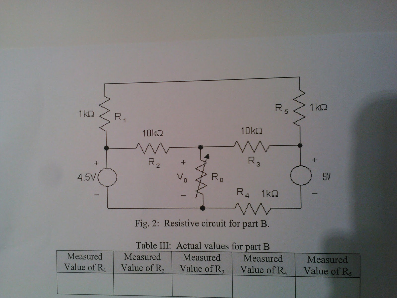
We started by building this circuit layout:


We are given the task to come up with a circuit that ranges between 0 and -10V which has to consume 1mA or less of current from a sensor that ranges from 0 to +1V. In other words, we have to build an inverting amplifier with a gain of -10.

Step 1A:
We need to first calculate Ri ( input resistance ), given that the voltage in the sensor ranges from 0 - 1V

V = iR, R = V/i = 1/0.001 = 1000 ohms

Step 1B:
Next we need to assign an Rf (feedback resistor),
R = V/i = 10/0.001 = 10,000 ohms

When we introduce our 'sensor', the circuit schematics will be slightly changed;


Step 1C:
Disconnecting the inverting amplifier, we can obtain Rx by assuming we want to operate it at half of its standard 1/4W power rating;

1/8 = 12^2/Rx, Rx = 1152ohms

Although we could not get an exact 1152 ohm resistor, we obtained a 1300 ohm resistor

Step 1D:
To find Ry, we use voltage divider in series for both Rx and Ry, provided that there's no loading in Ry and that there's 1V across Ry;

1 = 12Ry/ (1152 + Ry), and Ry = 104.72, using 130 ohm resistor

Step 1E:
Next, we need to find Rth for the circuit
1/1152 + 1/104.72 = 1/Rth
Rth = 96 ohms

Step 1F:
We found out that the Thevenin Resistance is NOT above at least a factor of 20 times smaller than Ri. This means that we'll need to choose a considerably larger value for Ri. Ri = 3,000 ohms  and Rf = 30,000 ohms.

Step 2: Measuring components


Component Nominal  Measured Rating
Ri 3000 ohms 2999+/-2 ohms  1/8
Rf 30000ohms 29998+/-2 ohms  1/8
Rx 1300 ohms 1299 +/-1 ohms  1/8
Ry 130 ohms 129+/-1 ohms  1/8
V1 12V 12.27+/- .1 V  2 amps 
V2 12V  12.27+/-.1 V  2amps 

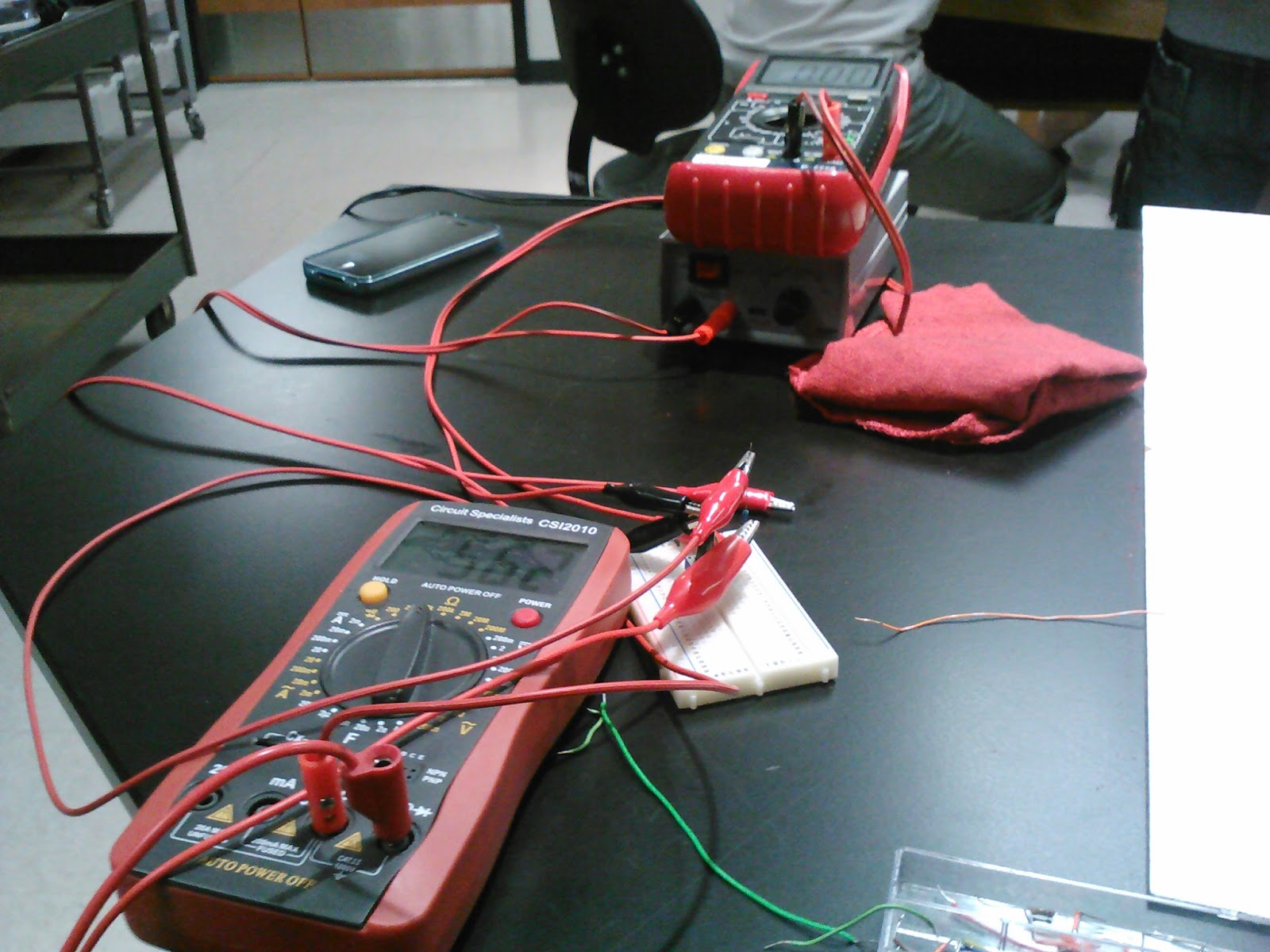
Step 3: Circuit overview


Step 4: Performing experiment


Vin (V) Vout (V) Gain Vri (V) Iri (mA) Vrf (V)
0.00 0 0 0 0 0
0.25 2.79+/-.01 0.0896+/-.00032 0.251+/-.001 0.0837+/-.00034 2.79+/-.02
0.50 5.55+/-.02 0.0901+/-.00032 0.494+/-.001 0.1647+/-.00035 5.49+/-.01
0.75 8.29+/-.02 0.0905+/-.00022 0.745+/-.002 0.2483+/-.00069 8.29+/-.01
1.00 10.71+/-.01 0.09337+/-.000087 .968+/-.001 0.3228+/-.00040 10.77+/-.02

We measured the current in V1 to be 0.96+/-.01mA and the current in V2 to be -1.29+/-.02mA.


Wednesday, April 3, 2013

PSpice Tutorial Problems

Problem 1:


Problem 2:

Circuit from problem 2

Graph from Problem 2

Max. Power = 7.4955W at RL = 3.5106 Ohms.

Maximum Power Transfer

In this experiment we study the concept of maximum power transfer within a circuit, and use this theorem to determine the Thevenin resistance of such circuit. The Maximum Power Transfer states that maximum power from circuit to resistive load will be achieved once load resistance = Rth.

First the following circuit is constructed:


where R0 is a variable resistor, in this case a potentiometer


Nominal  Measured
Resistor 5.6 Kohm 5.62+/-.02 Kohm
Voltage source 4.5 V 4.54 V


The potentiometer was varied so that we could get readings of voltage and resistance coming from a wire attached to the potentiometer. 


After getting values for voltage and resistance, we can compute the power through the potentiometer.

Measured V0 (V) Measured Rx (Kohms) Calculated P0 (W)
2.80+/-.01 14.64+/-.01 0.000536+/-.0000028
2.68+/-.02 13.73+/-.01 0.000523+/-.0000055
2.51+/-.01 12.55+/-.02 0.000502+/-.0000029
2.43+/-.01 12.08+/-.01 0.000488+/-.0000028
2.32+/-.02 11.50+/-.01 0.000468+/-.0000058
2.17+/-.01 10.77+/-.01 0.000437+/-.0000029
1.98+/-.01 10.00+/-.01 0.000392+/-.0000028
1.80+/-.02 9.34+/-.01 0.000347+/-.0000055
1.63+/-.02 8.78+/-.02 0.000303+/-.0000053
1.41+/-.01 8.17+/-.02 0.000244+/-.0000025
1.28+/-.01 7.82+/-.01 0.000210+/-.0000023
0.84+/-.01 6.89+/-.01 0.000103+/-0000017
.02+/-.01 5.65+/-.02 0.00000007+/-.00000
.00+/-.001 5.62+/-.02 ~0

Analyzing the Thevenin equivalent circuit, we can calculate the theoretical voltage and power going through the potentiometer using voltage division;

where x is the value at which the potentiometer is set for every voltage.

Theoretical V0 (V) Theoretical Power (W)
3.25 0.000721
3.20 0.000746
3.11 0.000771
3.07 0.000780
3.03 0.000798
2.96 0.000814
2.88 0.000829
2.81 0.000845
2.75 0.000861
2.67 0.000873
2.62 0.000878
2.48 0.000893
2.26 0.000904
2.25 0.000901


Looking at Fig. 2, we can observe that:

Max Power (0.536KW) occurs at 14.64kohms.

To get the theoretical value of the resistance at which max. power occurs, we solve for R in P = v^2/R, where the voltage is 2.80V (voltage at which max. power happens);

R = 2.80^2/0.000536 = 14626.87 ohms

% Error = 0.137%

Part B:
For the second part of this experiment we used Logger Pro software to obtain a graph of power. The circuit, however, was a little bit more complex;


Nominal (kohms) Measured (kohms)
R1 1 0.966
R2 10 9.85
R3 10 9.86
R4 1 0.976
R5 1 0.979


Nominal (V) Measured (V)
Voltage source 1 4.5 4.54+/-.01
Voltage source 2 9 9.05+/-.01

Logger Pro Graph Power vs. T

The power graph was obtained by dictating a function that multiplies voltage and current. Unfortunately, the graphs for voltage and current were less than satisfactory due to the amount of error and the sensitivity of the probes.


Notice the spikes on the voltage graph

This results compromised the data analysis for this part.