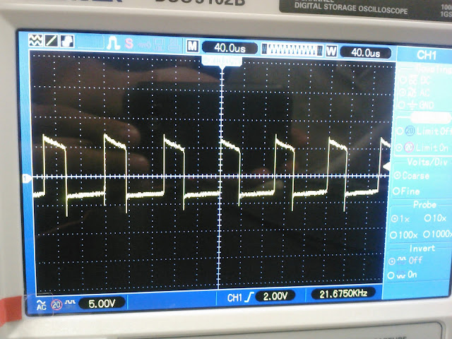
We used a function generator as well as an oscilloscope to obtain graphs.
Flyback Voltage
In the first part we tested flyback voltage which consisted on just the motor and a 2.2 Kohm resistor.We set up the oscilloscope for single sweep with vertical scale of 10v/div and time scale of 0.1 ms/div.
We obtained the following graph:
A 1N4007 diode was adapted to the circuit so that it could correct the noise in the graph.
We noticed that even with the diode, we could still see the flaws on the graph (eg. the sharp, uneven peaks).
We also noticed that the diode would get warm after the motor was left running for a long period of time.
Open Loop MOSFET Voltage Control Unit
On the following part, we studied the effects of adding a MOSFET transistor which it's an analog of the variable transistor; source voltage controlled resistance. The function of a MOSFET is to control the flow of current in the Source and Drain leads which is governed by the Gate voltage. We also added a potentiometer that allowed us to change the resistance, and hence vary the voltage (gate voltage of MOSFET) on the motor.
Looking at the formula;
Rds = VdRl / (Vs-Vd)
we can see that Rl (in this case the motor), is driven by the resistance of the MOSFET. And since the MOSFET behaves as a variable resistor, we can control it via the potentiometer. We also see that when the voltage drain is smaller than the voltage source Vs, the ratio Vd/(Vs-Vd) decreases as Vd decreases.
When we attempted to slowly increase the voltage gate from zero, it was quite difficult to have steady control of the motor. The voltage was fluctuating rapidly in short periods of time.
We measured the motor DC internal resistance to be 2.5 ohms.
Part 2: PWM Chopper MOSFET Motor Control
In the last part of this experiment we analyzed how motors act when a pulse is applied to them. In a broad picture, pulses continously turn on and off the motor in a periodic matter.The motor was fed by a function generator instead of a potentiometer, and it was set to generate a square wave.
When we reduced the frequency from 10 to 6.73 Khz we noticed that the motor emitted pulses
The duty cycle of the square wave was varied from 0 to 100% resulting in the motor's rotation decrease in speed.
Looking at the waves and the motor rotation, there was clearly an addition of waves going on.
We found the time it took for the motor to go to 100 to 0% duty cycle and reach minimum speed: ~ 1 second.


No comments:
Post a Comment